FID diagram wanted
Posted: Fri Dec 23, 2016 8:22 pm
So I have read on the Restek website that "At elevated temperatures, even trace levels of oxygen or water will quickly cause irreversible damage to the stationary phase... To prevent oxygen and moisture from entering the system and damaging the column, the system must be completely leak free. In addition, the carrier gas must be passed through a high-quality oxygen trap before entering the column."
What prevents oxygen and moisture from the room entering through the rear of the column though the FID when the GC is turned off?
I understand how the inlet is sealed between the septum at the injection port and the ferrule around the column. The part I do not understand is how the FID remains sealed. I can see the moisture that is being produced from the flame when I hold a cool watch glass and see condensation. Is there some form of port that allows the exhaust to escape but then remains sealed when the FID is not in use? And if such a port exists, why can I not see it in the diagrams available online?
This is on par with everything I can find by a google image search.
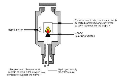
Does anyone possess or know where to find a more technical schematic?
Thank you.
What prevents oxygen and moisture from the room entering through the rear of the column though the FID when the GC is turned off?
I understand how the inlet is sealed between the septum at the injection port and the ferrule around the column. The part I do not understand is how the FID remains sealed. I can see the moisture that is being produced from the flame when I hold a cool watch glass and see condensation. Is there some form of port that allows the exhaust to escape but then remains sealed when the FID is not in use? And if such a port exists, why can I not see it in the diagrams available online?
This is on par with everything I can find by a google image search.
Does anyone possess or know where to find a more technical schematic?
Thank you.