The following is a step by step description of the automated process of detecting an extinguished flame and reigniting it.
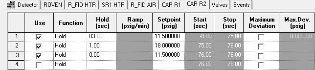
(In the figure below the hydrogen carrier pressure for the right FID is increased for 1 second at 75 seconds in the method and then set back to the original pressure.)
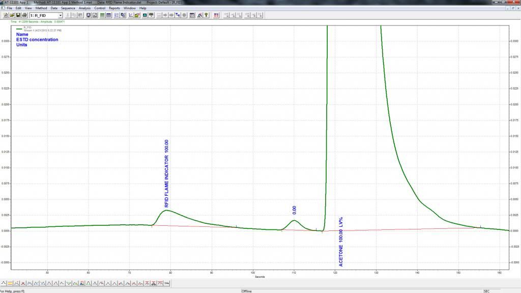
(The image below displays the response observed on the detector when the flame is lit.)
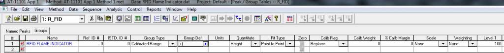
In the method the peak is integrated as a group based on its height to generated a response factor.
(In the figure below the RFID Flame Indicator group is defined from 75 to 90 seconds and is configured to quantitate height.)
At the end of each cycle this value is stored in the results table in System Manager and is compared to the limit it is referenced to.
(In the image below the value in the column "limitapp & limitref" for the RFID Flame Indicator result is "1 && 923" meaning application 1, limit 923.)

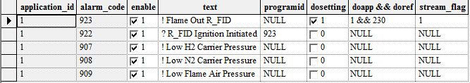
(Below is the limit table for application 1. Limit 923 named Flame Out R_FID is configured as a lo value limit with a value of 10 and is referenced to application 1, alarm 923.)

When the Flame Indicator result value is compared to the value of the limit and found to be less the alarm referenced by the limit is activated.
When activated it posts an alarm to the flowing stream as well as enables the manual ignite digital output for the FID.
(Below is the alarmhandler table for application 1. Alarm 923 named !Flame Out R_FID is configured to enable digital ouput 230 when activated.)
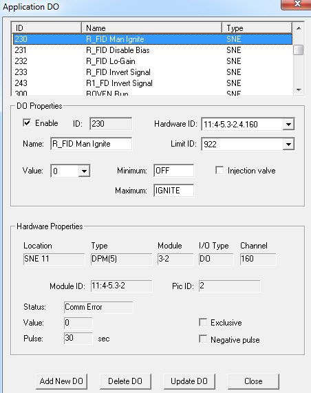
When the alarm activates the manual ignite digital output for the FID it will begin to pulse the glow plug for 30 seconds and will also activate a second a second alarm which is referenced to a limit dependent upon the logical state of the manual ignite digital output for the the FID.
(In the application DO table below the R_FID manual ignite digital output 230 is configured to pulse for 30 seconds and references limit 922.)
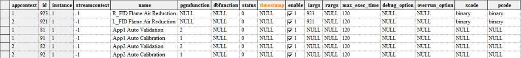
When the second alarm called !R_FID Ignition Initiated is activated by the manual ignite digital output it posts the alarm and runs a Max Basic program.
(In the alarm handler table below it can be seen that alarm 922 !R_FID Ignition Initiated is configured to run program 923.)
The Max Basic program reduces the normal flame air pressure by half in order to create a more hydrogen rich fuel ratio to aid in the ignition of the flame.
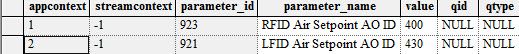
(The program table is shown below and program 923 is named R_FID Flame Air Reduction and has a iarg value of 923. The value 923 points to the value of parameter 923 in the parameters table.)
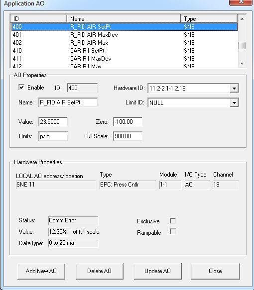
(Parameter 923 in the figure below named RFID Air Setpoint AO has a value of 400 which is the analog output id for the R_FID Air Pressure Setpoint.)
(The current setpoint for the R_FID Air is 23.5 psig, therefore the program will reduce the pressure setpoint to 11.75 psig.)
At the end of the 30 second duration the ignitor has been pulsed the flame should now be lit.
However the FID air pressure is still at half its normal operating pressure.
Therefore the last task in the process is to set the air pressure back to its normal operating pressure in the method.
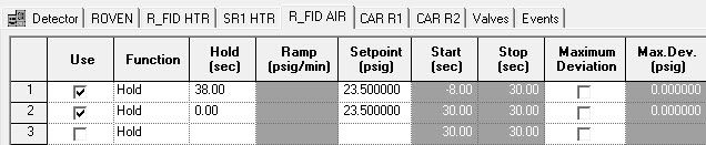
(The image below shows how the R_FID Air pressure is set at 30 seconds in the method.)
If you have any further questions or are still experiencing problems getting the flame to ignite please let me know.


